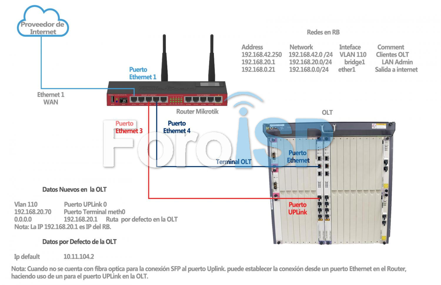
Actualmente la red tiene esta estructura:
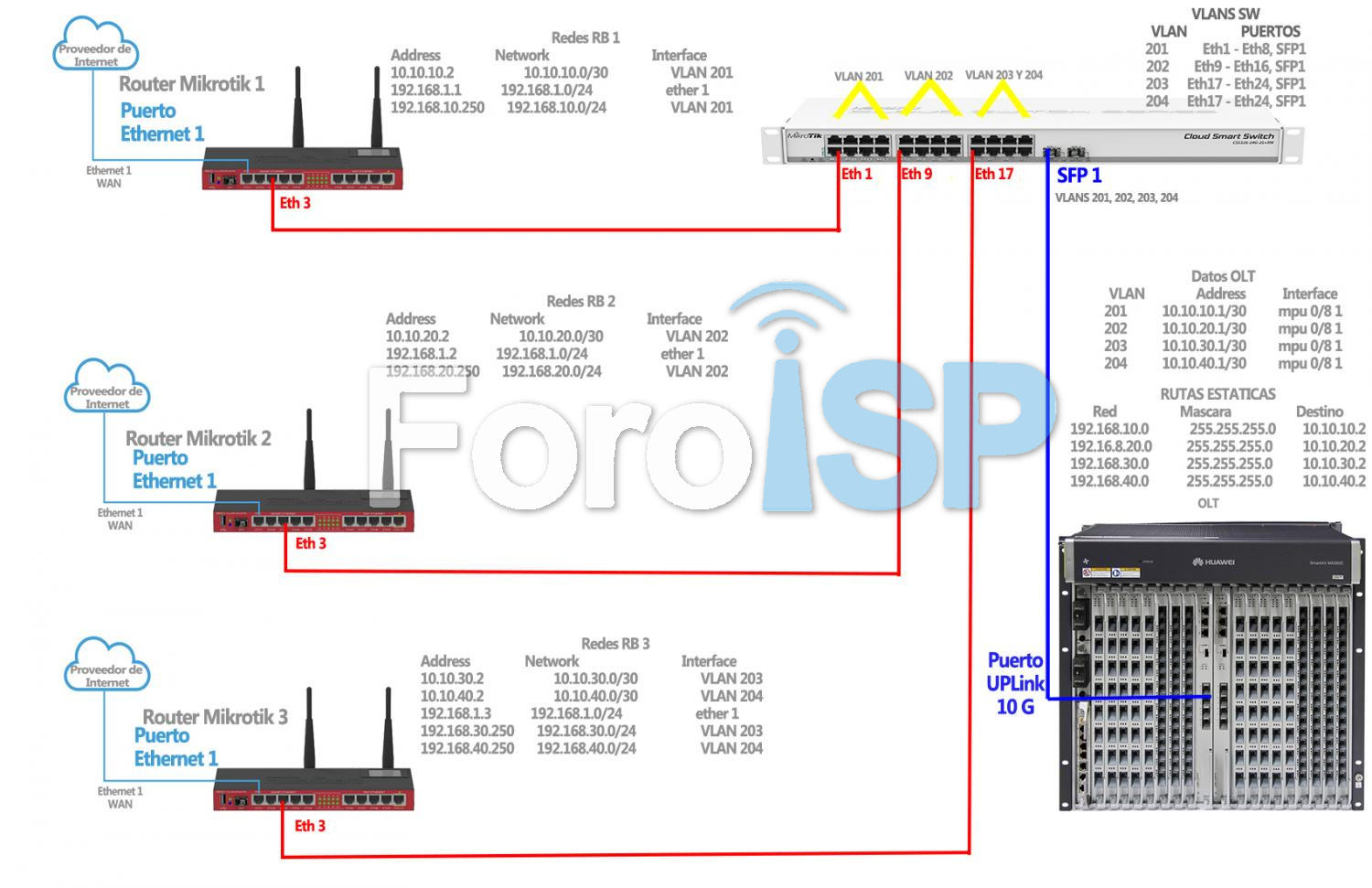
En este manual se busca llegar a la siguiente estructura de red:
Detalles:
Nota
- Se conectará 3 RB Mikrotik a la OLT por medio de un puerto UPLink 10G, esto para aprovechar la capacidad(10G) del puerto
- Para realizar la conexión de 3 RB a un puerto UPLink es necesario un Switch capa 2 con capacidad de manejo de VLANs (En este ejemplo se usará un Cloud Smart Switch CSS326-24G-2S+RM de Mikrotik)
- Para hacer más optima la red, el trafico será dividido en 4 VLANs, los primeros 2 RB tendrán 1 VLAN cada uno y el tercer RB tendrá 2 VLANs
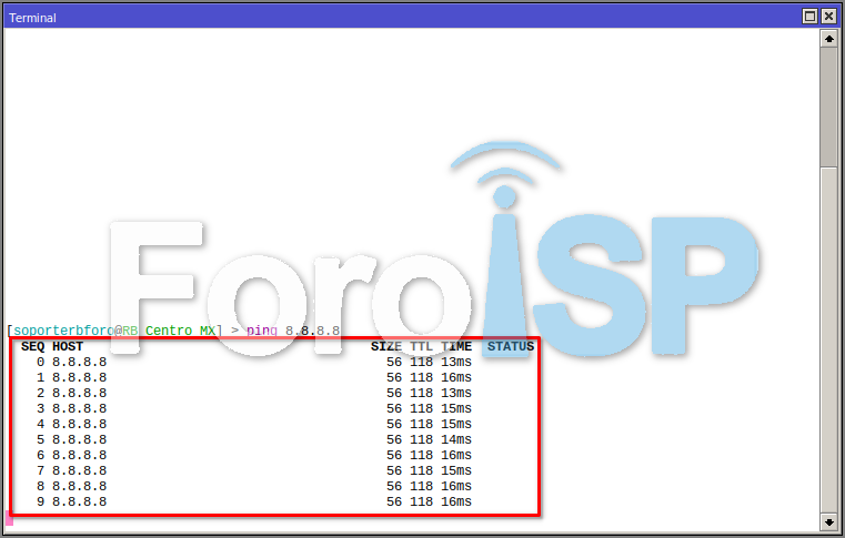
1 Debemos comprobar que tengamos salida a internet en Mikrotik
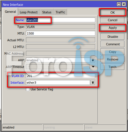
2 Crear VLAN
Se agregará la VLAN 201 del RB 1
Para agregar la VLAN al RB por winbox, ingresaremos a Interfaces > VLAN y daremos click +
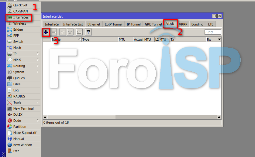
Y agregamos los siguientes datos para agregar la VLAN 201
3 Crear Redes RB
Se agregarán la redes siguiendo el diagrama presentado anteriormente
Para agregar redes por winbox, ingresamos a IP > Address y daremos click +
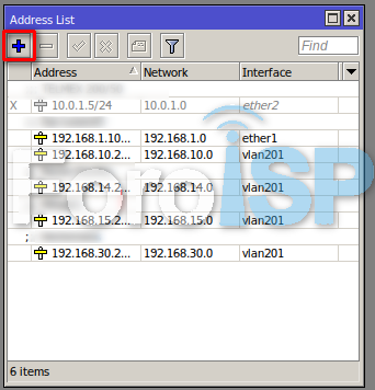
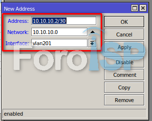
Y pondremos los datos de las redes
En este ejemplo agregaremos la primera RED del diagrama 10.10.10.2
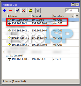
Al final tendremos estas redes
4 Agregar rutas RB
Debemos agregar rutas en el RB para que la red LAN (En este ejemplo en el rb 1 la red LAN es 192.168.10.0/24) pueda enrutarse a la OLT por medio de la red 10.10.10.0/30, dirigiendo el trafico es esta red LAN a la IP 10.10.10.1, la cual es una de las IP que se pondrán en la OLT.
Para agregar rutas por winbox, ingresamos a IP > Routes y daremos click en +
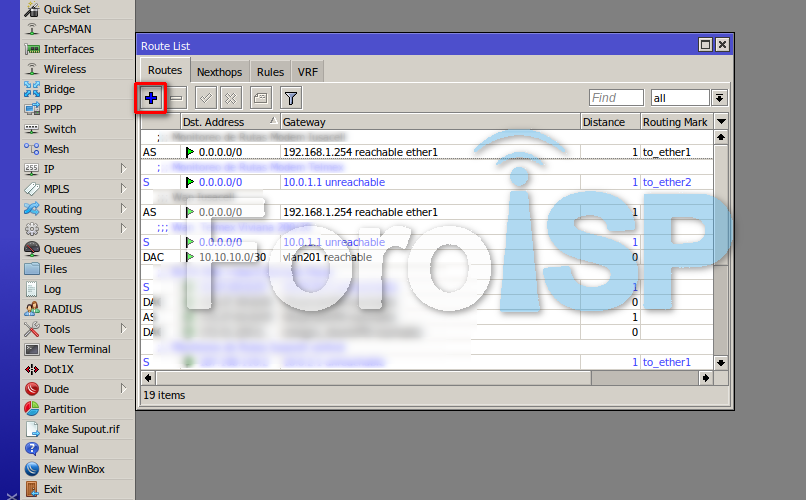
Posteriormente agregaremos los siguientes datos.
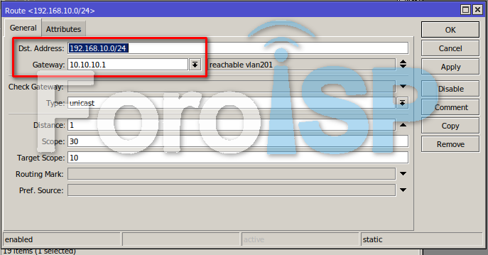
Deben crearse la siguiente ruta
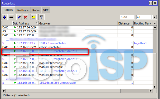
Rutas a crear en RBs Mikrotik
- RB 1
- Dst. Address: 192.168.10.0/24
- Gateway: 10.10.10.1
- RB 2
- Dst. Address: 192.168.20.0/24
- Gateway: 10.10.20.1
- RB 3
- Ruta 1
- Dst. Address: 192.168.30.0/24
- Gateway: 10.10.30.1
- Ruta 2
- Dst. Address: 192.168.40.0/24
- Gateway: 10.10.40.1
Nota
Repetir los pasos 1, 2, 3 y 4 en los demas RB de acuerdo al diagrama
5 Nos conectamos por telnet con la IP
/sys telnet 192.168.20.70

root

admin123
6 Entramos a modo de configuración
MA5800>enable

MA5800#config
7 Crear VLANs y asignarlas al puerto UPLink 0/8 1
VLAN 201
MA5800(config)#vlan 201 smart

MA5800(config)#port vlan 201 0/8 1

MA5800(config)#interface mpu 0/8

MA5800(config-if-mpu-0/8)#native-vlan 1 vlan 201
VLAN 202
MA5800(config)#vlan 202 smart

MA5800(config)#port vlan 202 0/8 1

MA5800(config)#interface mpu 0/8

MA5800(config-if-mpu-0/8)#native-vlan 1 vlan 202
VLAN 203
MA5800(config)#vlan 203 smart

MA5800(config)#port vlan 203 0/8 1

MA5800(config)#interface mpu 0/8

MA5800(config-if-mpu-0/8)#native-vlan 1 vlan 203
VLAN 204
MA5800(config)#vlan 204 smart

MA5800(config)#port vlan 204 0/8 1

MA5800(config)#interface mpu 0/8

MA5800(config-if-mpu-0/8)#native-vlan 1 vlan 204
8 Asignar IP a VLAN
VLAN 201
MA5800>enable

MA5800#config

MA5800(config)#interface vlanif 201

MA5800(config)#ip address 10.10.10.1

MA5800(config)#quit
VLAN 202
MA5800>enable

MA5800#config

MA5800(config)#interface vlanif 202

MA5800(config)#ip address 10.10.20.1

MA5800(config)#quit
VLAN 203
MA5800>enable

MA5800#config

MA5800(config)#interface vlanif 203

MA5800(config)#ip address 10.10.30.1

MA5800(config)#quit
VLAN 204
MA5800>enable

MA5800#config

MA5800(config)#interface vlanif 204

MA5800(config)#ip address 10.10.40.1

MA5800(config)#quit
9 Crear Rutas en OLT
MA5800>enable

MA5800#config

MA5800(config)#ip route-static 192.168.10.0 255.255.255.0 10.10.10.2

MA5800(config)#ip route-static 192.168.20.0 255.255.255.0 10.10.20.2

MA5800(config)#ip route-static 192.168.30.0 255.255.255.0 10.10.30.2

MA5800(config)#ip route-static 192.168.40.0 255.255.255.0 10.10.40.2

MA5800(config)#save
10 Crear VLANS en Switch
Se deben crear las vlans en el switch, para est ejemplo se usará un Cloud Smart Switch CSS326-24G-2S+RM de Mikrotik, por defecto la ip de configuracion de este es 192.168.88.1 el usario es admin y NO TIENE CONTRASEÑA
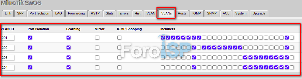
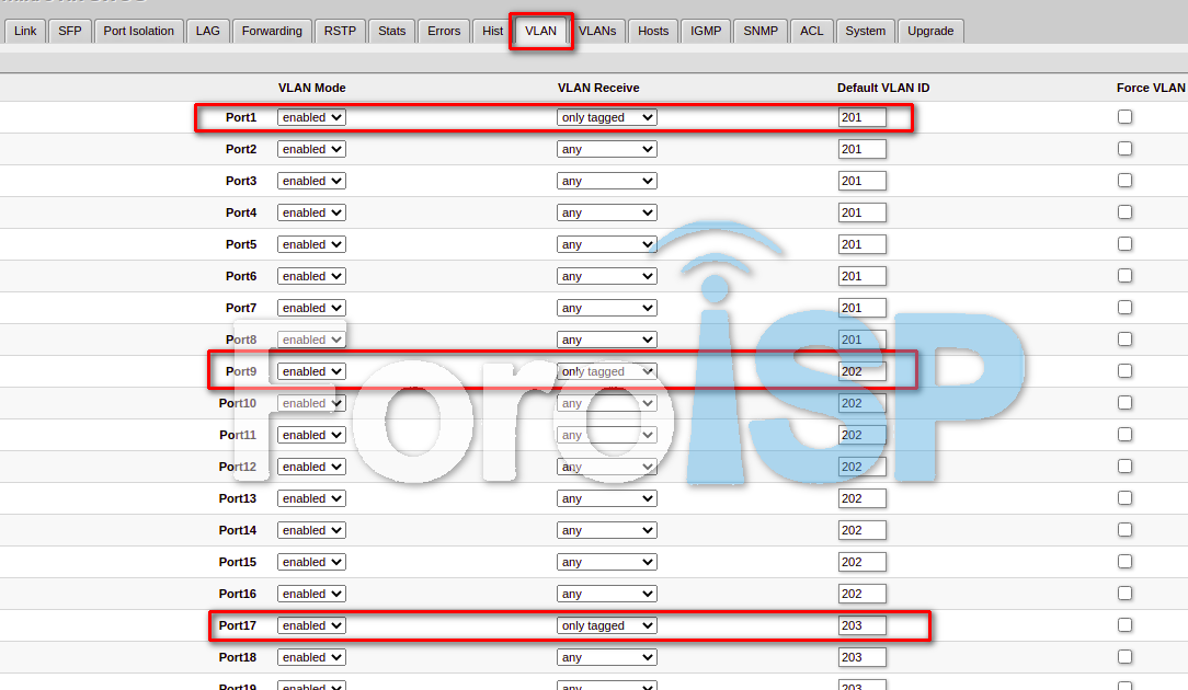
11 Configurar puertos switch
Por último es necesario configurar los puertos 1, 9 y 17, para que solo ingresen vlans tagged y habilitar el filtrado de vlans.
Lo anterior se hará en el menú VLAN.

 Gracias:
  Me agrada:
  Me desagrada:


 Citar
Citar