El siguiente es una continuación de este otro manual. El laboratorio ha sido virtualizado en Eve-ng para ejemplificar como distribuir un prefijo de red sobre varias sucursales.
El prefijo utilizado es el destinado para documentación de IPv6, por lo que el laboratorio no cuenta con salida a internet, aunque para efectos de este manual no es necesario contar con internet en las máquinas.
Nota
Todos los equipos usados en el laboratorio son imagenes de RouterOS, con ello se podrá ejemplificar el funcionamiento de routers, switches y la configuración del cliente final
El prefijo 2001:db8::/32 se utiliza para documentación de IPv6, para este ejercicio hemos partido el prefijo /32 en un prefijo /48, el prefijo se distribuirá entre un router principal y dos routers sucursales.
Configuración de Router Sucursal Principal
1 Direccionamiento de las interfaces
Primero debemos colocar las direcciones ipv6 dentro de las interfaces del router principal de la organización.
/ipv6 address

add address=2001:db8:aaaa:f0ca::bebe advertise=no comment=Enlace-to-Carrier interface=ether1

add address=2001:db8:cafe:c000::f0ca/56 advertise=no comment=Enlace-to-Sucursal-1 interface=ether2

add address=2001:db8:cafe:d000::f0ca/56 advertise=no comment=Enlace-to-Sucursal-2 interface=ether3
2 Agregar rutas de Router Sucursal Principal
/ipv6 route

add check-gateway=ping comment="INTERNET CARRIER" distance=1 gateway=2001:db8:aaaa:f0ca::f0ca

add comment=Sucursal-1-VLAN-10 distance=1 dst-address=2001:db8:cafe:c100::/56 gateway=2001:db8:cafe:c000::bebe

add comment=Sucursal-1-VLAN-11 distance=1 dst-address=2001:db8:cafe:c200::/56 gateway=2001:db8:cafe:c000::bebe

add comment=Sucursal-1-VLAN-12 distance=1 dst-address=2001:db8:cafe:c300::/56 gateway=2001:db8:cafe:c000::bebe

add comment=Sucursal-1-VLAN-13 distance=1 dst-address=2001:db8:cafe:c400::/56 gateway=2001:db8:cafe:c000::bebe

add comment=Sucursal-1-VLAN-14 distance=1 dst-address=2001:db8:cafe:c500::/56 gateway=2001:db8:cafe:c000::bebe

add comment=Sucursal-1-VLAN-15 distance=1 dst-address=2001:db8:cafe:c600::/56 gateway=2001:db8:cafe:c000::bebe

add comment=Sucursal-2-VLAN-20 distance=1 dst-address=2001:db8:cafe:d100::/56 gateway=2001:db8:cafe:d000::bebe

add comment=Sucursal-2-VLAN-21 distance=1 dst-address=2001:db8:cafe:d200::/56 gateway=2001:db8:cafe:d000::bebe

add comment=Sucursal-2-VLAN-22 distance=1 dst-address=2001:db8:cafe:d300::/56 gateway=2001:db8:cafe:d000::bebe

add comment=Sucursal-2-VLAN-23 distance=1 dst-address=2001:db8:cafe:d400::/56 gateway=2001:db8:cafe:d000::bebe

add comment=Sucursal-2-VLAN-24 distance=1 dst-address=2001:db8:cafe:d500::/56 gateway=2001:db8:cafe:d000::bebe

add comment=Sucursal-2-VLAN-25 distance=1 dst-address=2001:db8:cafe:d600::/56 gateway=2001:db8:cafe:d000::bebe
Configuración de Router Sucursal 1
1 Creación de VLANs
Debido a que simularemos el funcionamiento de un router dando servicio a una OLT, vamos a crear VLANs para el servicio de los abonados.
/interface vlan

add interface=ether2 name=vlan-10 vlan-id=10

add interface=ether2 name=vlan-11 vlan-id=11

add interface=ether2 name=vlan-12 vlan-id=12

add interface=ether2 name=vlan-13 vlan-id=13

add interface=ether2 name=vlan-14 vlan-id=14

add interface=ether2 name=vlan-15 vlan-id=15
2 Direccionamiento de Router Sucursal 1
/ipv6 address

add address=2001:db8:cafe:c000::bebe/56 advertise=no comment=Enlace-to-Sucursal-Principal interface=ether1

add address=2001:db8:cafe:c100::1/56 advertise=no comment=VLAN-10 interface=vlan-10

add address=2001:db8:cafe:c200::1/56 advertise=no comment=VLAN-11 interface=vlan-11

add address=2001:db8:cafe:c300::1/56 advertise=no comment=VLAN-12 interface=vlan-12

add address=2001:db8:cafe:c400::1/56 advertise=no comment=VLAN-13 interface=vlan-13

add address=2001:db8:cafe:c500::1/56 advertise=no comment=VLAN-14 interface=vlan-14

add address=2001:db8:cafe:c600::1/56 advertise=no comment=VLAN-15 interface=vlan-15
3 Agregar ruta por defecto en Sucursal 1
/ipv6 route add comment=INTERNET-to-Sucursal-Principal distance=1 gateway=2001:db8:cafe:c000::f0ca
4 Crear servidor PPPoE
Para simular el servicio de un abonado, configuraremos un servicio PPPoE colocado sobre las interfaces VLAN que podemos usar en las OLT.
/interface pppoe-server server

add disabled=no interface=vlan-10 service-name=PPPoE-VLAN-10

add disabled=no interface=vlan-11 service-name=PPPoE-VLAN-11

add disabled=no interface=vlan-12 service-name=PPPoE-VLAN-12

add disabled=no interface=vlan-13 service-name=PPPoE-VLAN-13

add disabled=no interface=vlan-14 service-name=PPPoE-VLAN-14

add disabled=no interface=vlan-15 service-name=PPPoE-VLAN-15
5 Crear un pool Ipv6
/ipv6 pool

add name=Pool-PPPoE-VLAN-10 prefix=2001:db8:cafe:c100::/56 prefix-length=64
6 Crear un profile pppoe
/ppp profile

add dhcpv6-pd-pool=Pool-PPPoE-VLAN-10 name=Dual-Stack-IPv4-IPv6 remote-ipv6-prefix-pool=Pool-PPPoE-VLAN-10
7 Generamos un pppoe secret para un abonado
/ppp secret

add local-address=10.10.10.1 name=abonado-1 password=123456789 profile=Dual-Stack-IPv4-IPv6 remote-address=10.10.10.10 remote-ipv6-prefix=2001:db8:cafe:c100::100/128 service=pppoe
8 Crear DHCP Server
/ipv6 dhcp-server

add address-pool=Pool-PPPoE-VLAN-10 interface=vlan-10 name=PPPoE-VLAN-10
Configuración de Router Sucursal 2
1 Creación de VLANs
/interface vlan

add interface=ether2 name=vlan-20 vlan-id=20

add interface=ether2 name=vlan-21 vlan-id=21

add interface=ether2 name=vlan-22 vlan-id=22

add interface=ether2 name=vlan-23 vlan-id=23

add interface=ether2 name=vlan-24 vlan-id=24

add interface=ether2 name=vlan-25 vlan-id=25
2 Direccionamiento de Router Sucursal 2
/ipv6 address

add address=2001:db8:cafe:d000::bebe/56 advertise=no comment=Enlace-to-Sucursal-Principal interface=ether1

add address=2001:db8:cafe:d100::1/56 advertise=no comment=VLAN-20 interface=vlan-20

add address=2001:db8:cafe:d200::1/56 advertise=no comment=VLAN-21 interface=vlan-21

add address=2001:db8:cafe:d300::1/56 advertise=no comment=VLAN-22 interface=vlan-22

add address=2001:db8:cafe:d400::1/56 advertise=no comment=VLAN-23 interface=vlan-23

add address=2001:db8:cafe:d500::1/56 advertise=no comment=VLAN-24 interface=vlan-24

add address=2001:db8:cafe:d600::1/56 advertise=no comment=VLAN-25 interface=vlan-25
3 Agregar ruta por defecto en Sucursal 2
/ipv6 route add comment=INTERNET-to-Sucursal-Principal distance=1 gateway=2001:db8:cafe:d000::f0ca
4 Crear servidor PPPoE
/interface pppoe-server server

add disabled=no interface=vlan-20 service-name=PPPoE-VLAN-20

add disabled=no interface=vlan-21 service-name=PPPoE-VLAN-21

add disabled=no interface=vlan-22 service-name=PPPoE-VLAN-22

add disabled=no interface=vlan-23 service-name=PPPoE-VLAN-23

add disabled=no interface=vlan-24 service-name=PPPoE-VLAN-24

add disabled=no interface=vlan-25 service-name=PPPoE-VLAN-25
5 Crear un pool Ipv6
/ipv6 pool

add name=Pool-PPPoE-VLAN-20 prefix=2001:db8:cafe:d100::/56 prefix-length=64
6 Crear un profile pppoe
/ppp profile

add dhcpv6-pd-pool=Pool-PPPoE-VLAN-20 name=Dual-Stack-IPv4-IPv6 remote-ipv6-prefix-pool=Pool-PPPoE-VLAN-20
7 Generamos un pppoe secret para un abonado
/ppp secret

add local-address=10.20.20.1 name=abonado-3 password=123456789 profile=Dual-Stack-IPv4-IPv6 remote-address=10.20.20.10 remote-ipv6-prefix=2001:db8:cafe:d100::100/128 service=pppoe
8 Crear DHCP Server
/ipv6 dhcp-server

add address-pool=Pool-PPPoE-VLAN-20 interface=vlan-20 name=PPPoE-VLAN-20
Configuración de OLT Sucursal 1
1 Crear bridge
Como no podemos simular el protocolo GPON de una OLT, vamos a colocar un Mikrotik RouterOS en donde configuraremos un bridge con las VLAN de servicio.
/interface bridge

add name=OLT-1 vlan-filtering=yes


/interface bridge port

add bridge=OLT-1 interface=ether1

add bridge=OLT-1 interface=ether2 pvid=10

add bridge=OLT-1 interface=ether3 pvid=11

add bridge=OLT-1 interface=ether4


/interface bridge vlan

add bridge=OLT-1 tagged=ether1 untagged=ether2 vlan-ids=10

add bridge=OLT-1 tagged=ether1 untagged=ether3 vlan-ids=11
Configuración de OLT Sucursal 2
1 Crear bridge
/interface bridge

add name=OLT-2 vlan-filtering=yes


/interface bridge port

add bridge=OLT-2 interface=ether1

add bridge=OLT-2 interface=ether2 pvid=20

add bridge=OLT-2 interface=ether3 pvid=21

add bridge=OLT-2 interface=ether4


/interface bridge vlan

add bridge=OLT-2 tagged=ether1 untagged=ether2 vlan-ids=20

add bridge=OLT-2 tagged=ether1 untagged=ether3 vlan-ids=21
Configuración de Abonado-1
Para simular la configuración de una ONT de cliente, colocamos un Mikrotik como dispositivo final.
1 Crear el cliente PPPoE
Desde la lista de interfaces damos click en el simbolo de "+" y escogemos la opción de "PPPoE Client", allí colocamos la configuración del secret generado en el Router Sucursal 1.
/interface pppoe-client

add add-default-route=yes disabled=no interface=ether1 name=abonado-1 password=123456789 user=abonado-1
2 Configurar el DHCP Client
/ipv6 dhcp-client

add interface=abonado-1 pool-name=ABONADO-1 request=prefix
Configuración de Abonado-3
1 Crear el cliente PPPoE
/interface pppoe-client

add add-default-route=yes disabled=no interface=ether1 name=abonado-3 password=123456789 user=abonado-3
2 Configurar el DHCP Client
/ipv6 dhcp-client

add interface=abonado-3 pool-name=ABONADO-3 request=prefix
Conclusión
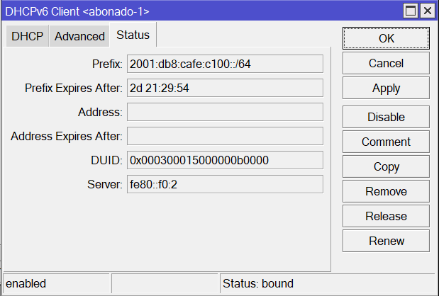
En cada abonado podemos consultar el status del prefijo recibido, esto mismo ocurre con una ONT dejada en casa de cliente final. Se recibe un prefijo, por lo regular un /64, con el que se otorga direccionamiento ipv6 para la casa del cliente.


 Gracias:
  Me agrada:
  Me desagrada:


 Citar
Citar
