OPCION 3 Sesión BGP ipv4 con carrier, entregando IP publicas a cliente comercial Con vlans
Descripción
En este escenario vamos a entregar las IPs publicas a los clientes comerciales atravez de una vlan ,en mi caso voy a utilizar la vlan 100, Vamos a empezar a configurar desde el ROUTER ENCORE ISP
Nota
No movemos configuración en ROUTER CARRIE ALESTRA y ROUTER BORDE
Paso 1Laboratorio
se realiza la reestructura del laboratorio BGP, para entregar las IP'S atravez de VLANS

PASO 2 Creacion de la VLAN
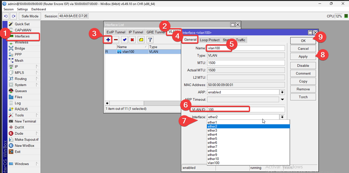
Habilitamos En este paso creamos la vlan que nos ayudara entregar las Ips publicas,Nos dirigimos a la pestaña interfaces, se abrirá una nueva ventana, esta ventana tiene varias pestañas, seleccionamos la pestaña VLAN. Se muestra la interface de VLAN y nos aparece un símbolo de +, damos clic en este símbolo y se abrirá una ventana nueva donde crearemos nuestras interfaces lógicas Vlans
 PASO 3Reasignar las IPs del ROUTER ENCORE
cambiamos la interfaz en lugar que sea ethernet 2 como anteriormente lo teniamos configurado , lo vamos a cambiar por la Vlan 100 que acabamos de crear
Por comando
/ip addressadd address=100.20.40.2/30 comment="PTP ROUTER BORDE ISP" interface=ether1 \
network=100.20.40.0
add address=15.20.3.1/24 comment="PREFIJO DE IP\B4S PUBLICAS" interface=\
vlan100 network=15.20.3.0
Por Interfaz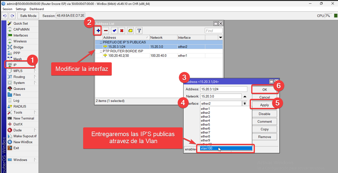
Nota
si ya cuentas con la ruta creada omite el paso 4
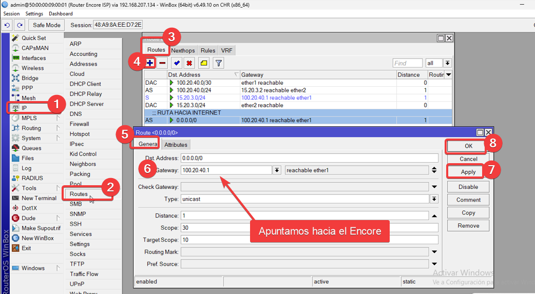
PASO4 Agregamos la ruta de internet
Habilitamos la ruta hacia internet apuntado a la IP de ROUTER BORDE ISP
0.0.0.0/0 Hacia el gateway 100.20.40.1
Por comandos
/ip route
add comment="RUTA INTERNET" distance=1 gateway=100.20.40.1
Por interfaz
PASO 5
Configuracion de las vlans en SW1-COMERCIAL
En este switch cisco io level 2 vamos a configurar las siguientes VLAN100
Nota
Puedes ocupar la marca del switch de tu preferencia
VLAN ID
|
Nombre de la VLAN
|
Puertos
|
| 100 |
VLAN 100 |
Ethernet 0 |
|
|
Los puertos que serán usados como troncales es el Ethernet 0 y la que sera como acceso sera el puerto Ethernet 1
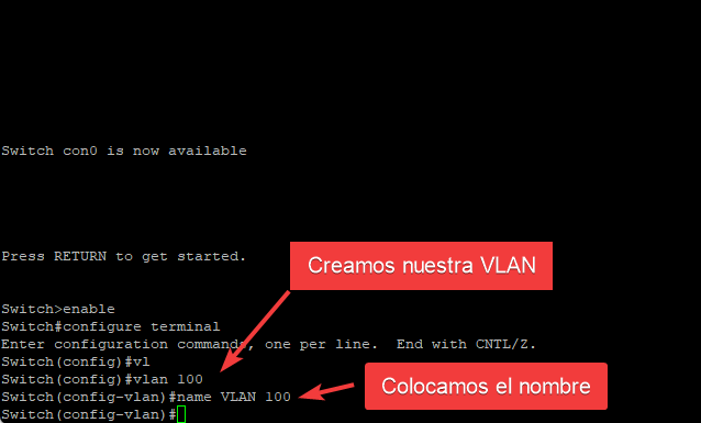
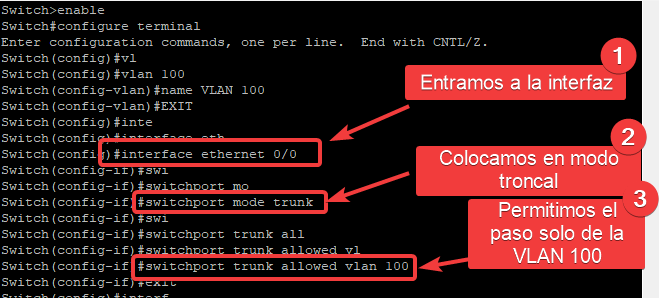
Creamos la vlan
entramos en modo configuración y agregamos los siguientes comandos
Comando
Enable
configure terminal
vlan 100
name VLAN 100
Ya que tenemos creado nuestra Vlan con su ID y Nombre toca asignarlo al puerto del switch, Entramos a la interface del switch, configuramos la interfaz Ethernet 0 que sea modo TRUNK y que permita la vlan
Comando
interface ethernet 0/0
switchport mode trunk
switchport trunk allowed vlan 100
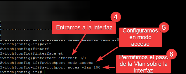
Seguidamente se configura en el Ethernet 1 la interfaz en modo acceso y permitimos su paso
 comandos
interface ethernet 0/1
switchport mode acces
switchport acces vlan 100
copy startup-config running-config
Nota
Recuerda que el switch guarda la informacion en la memoria volatil, tenemos que guardarlo en la memoria NVRAM
Comando
copy startup-config running-config
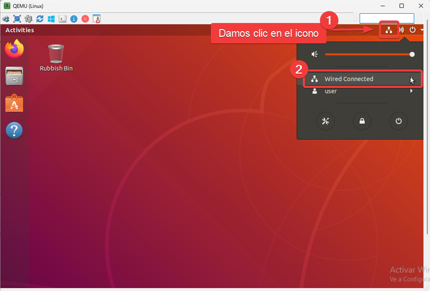
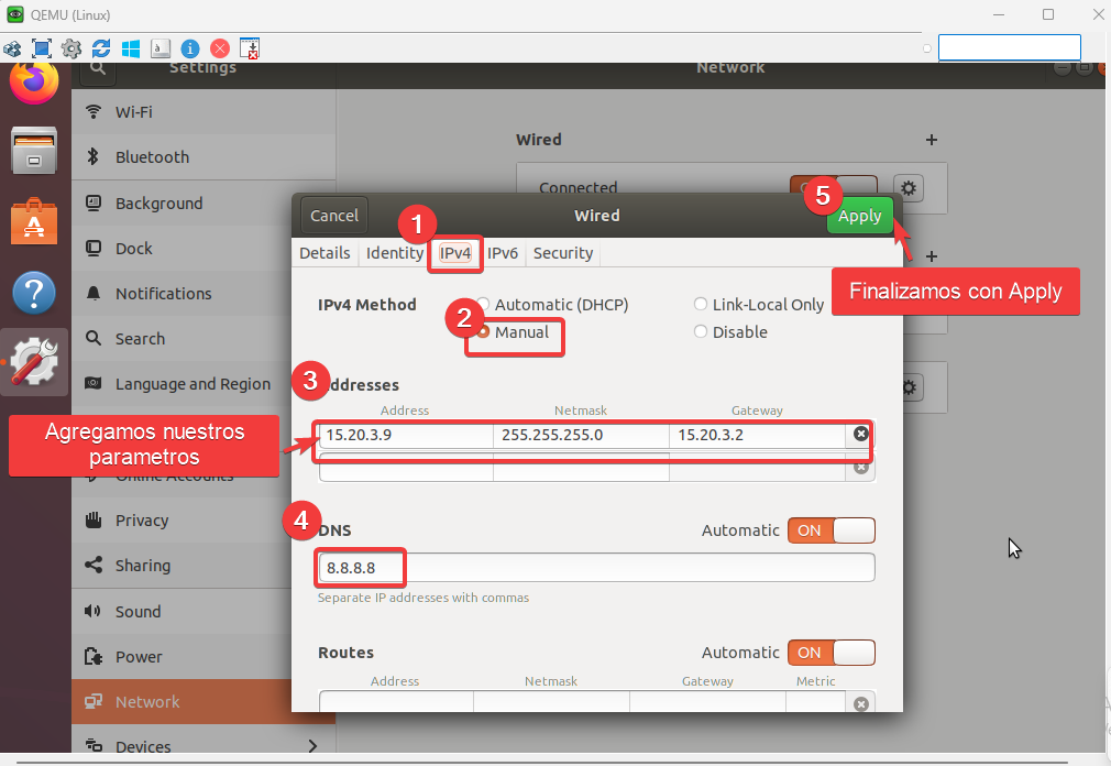
PASO[NUMERO_PASO]6[/NUMERO_PASO] Configuracion de la PC CLIENTE COMERCIAL
[NOTA_ADVERTENCIA]En este punto tu PC debe ya estar configurada y deberia tener internet, si no esta configurada seguimos los pasos[/NOTA_ADVERTENCIA]
Abrimos nuestra PC CLIENTE RESIDENCIAL y nos dirigimos en la red Wired connected , asi como se visualiza en la siguiente imagen
 Habilitamos la red y damos clic en ajustes
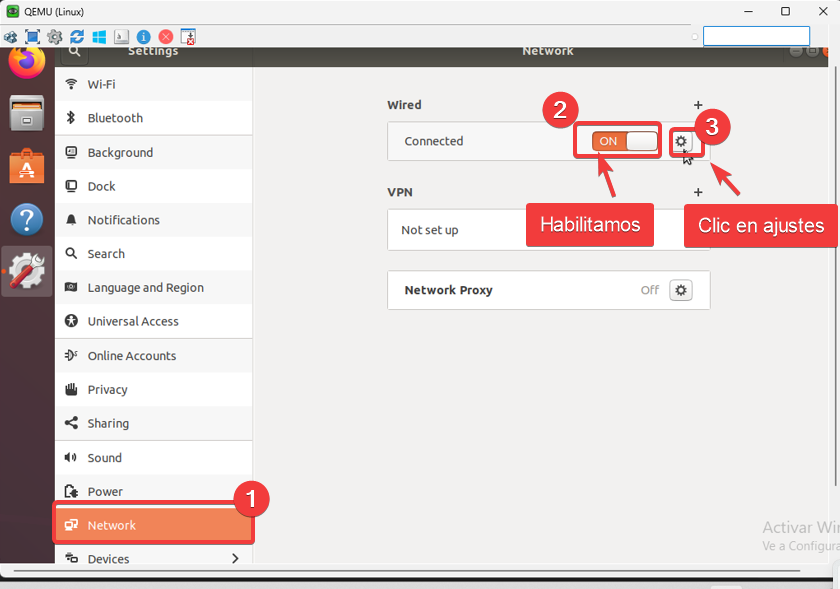 Agregamos una ip de la red de segmento que declaramos en Ether 2 de nuestro ROUTER ENCORE ISP
Parametros
IP ADRRESS :15.20.3.9
MASCARA 255.255.255.0
GATEWAY:15.20.3.1
DNS :8.8.8.8
Una vez que ya este declarado damos clic en apply
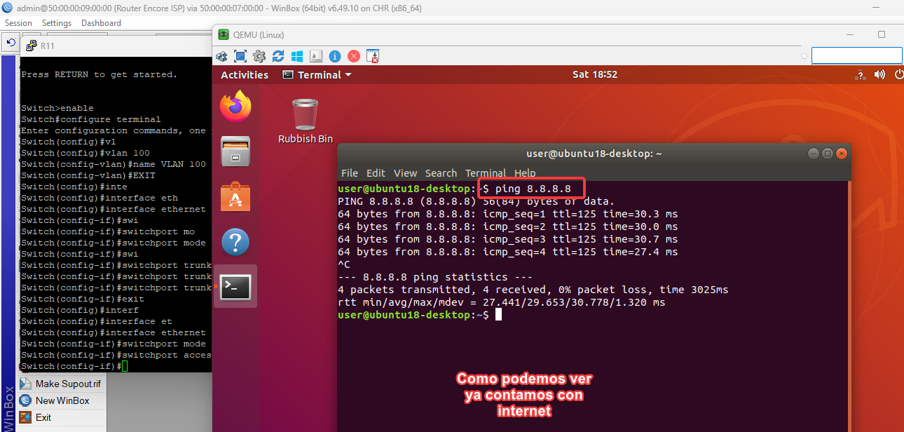
 PING
PING
Probamos que tengamos salida hacia internet
ROUTER CARRIER ALESTRA
/interface wireless security-profiles
set [ find default=yes ] supplicant-identity=MikroTik
/routing bgp instance
set default as=100 redistribute-connected=yes
/ip address

add address=100.200.20.1/30 comment="PTP AL ROUTER BORDE ISP" interface=\

    ether2 network=100.200.20.0
/ip dhcp-client
add disabled=no interface=ether1
/ip firewall nat

add action=masquerade chain=srcnat out-interface=ether1
/routing bgp network
add network=100.200.20.0/30 synchronize=no
/routing bgp peer

add default-originate=always name=Peer-to-RouterBordeISP remote-address=\

    100.200.20.2 remote-as=200 remove-private-as=yes
/system identity
set name="Carrier Alestra"
/tool romon
set enabled=yes
ROUTER BORDE
/interface vlan
add interface=ether3 name=vlan100 use-service-tag=yes vlan-id=100
/interface wireless security-profiles
set [ find default=yes ] supplicant-identity=MikroTik
/routing bgp instance

set default as=200 comment="AS ROUTER BORDE ISP"
/ip address
add address=100.200.20.2/30 comment="PTP AL ROUTER CARRIER ALESTRA" \
interface=ether2 network=100.200.20.0
add address=100.20.40.1/30 comment="PTP-ROUTER ENCORE ISP" interface=ether3 \
network=100.20.40.0
/ip dhcp-client
add disabled=no interface=ether1
/ip dns
set servers=8.8.8.8
/ip firewall nat
add action=accept chain=srcnat out-interface=ether2
/ip route
add comment="Pool /24 Route Static" distance=1 dst-address=15.20.3.0/24 \
gateway=100.20.40.2
/routing bgp network
add network=15.20.3.0/24 synchronize=no
add network=100.20.40.0/30 synchronize=no
/routing bgp peer

add name="Peer-To-Carrier Alestra" remote-address=100.200.20.1 remote-as=100
/system identity
set name="Router Borde ISP"
/tool romon
set enabled=yes
Router Encore
/interface vlan
add interface=ether2 name=vlan100 vlan-id=100
/interface wireless security-profiles
set [ find default=yes ] supplicant-identity=MikroTik
/routing ospf instance
set [ find default=yes ] disabled=yes router-id=1.1.1.1
/ip address
add address=100.20.40.2/30 comment="PTP ROUTER BORDE ISP" interface=ether1 \
network=100.20.40.0
add address=15.20.3.1/24 comment="PREFIJO DE IP\B4S PUBLICAS" interface=\
vlan100 network=15.20.3.0
/ip dhcp-server network
add address=15.20.3.0/24 dns-server=8.8.8.8 gateway=15.20.3.1
/ip dns
set servers=8.8.8.8
/ip route
add comment="RUTA HACIA INTERNET" distance=1 gateway=100.20.40.1
add distance=1 dst-address=15.20.3.0/24 gateway=100.20.40.1
add distance=1 dst-address=100.20.40.0/24 gateway=15.20.3.2
/system identity
set name="Router Encore ISP"
/tool romon
set enabled=yes
SW-1
hostname SW1
vlan 100
name VLAN 100
interface ethernet 0/0
switchport trunk encapsulation dot1q
switchport mode trunk
switchport trunk allowed vlan 100
interface ethernet 0/1

switchport mode acces

switchport acces vlan 100

copy startup-config running-config
Archivos descargables
Aqui puedes decargar el laboratorio
_Exports_unetlab_export-20250304-164615.zip

 Gracias:
  Me agrada:
  Me desagrada:


Habilitamos la red y damos clic en ajustes
En otro escenario si nuestra ruta no esta anuncia en ROUTER BORDE ISP ¿Dejariamos de tener internet?

 Citar
Citar